Resources
Books
Videos
Ajith
This page describes the usage of ExpEYES-17 on an Android phone, using the software named SEElab-3. An updated version of ExpEYES hardware has been released as SEELab-3. Software is common for both the devices.
More detailed information can be found at:
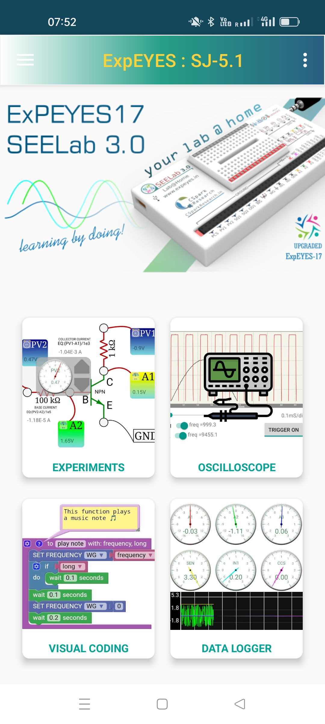
You can install the SEELAB-3 App from Google Play Store.
Open the App and connect the device to the USB port of the phone using an OTG cable (different types of OTG cables are used for microUSB and C type ports). On plugging in the device the LED should glow (In some versions of Android, you need to enable OTG from the Settings). The program will ask for permission to “Access the MCP2200 USB Serial Port Emulator”. If the connections are proper, after granting the permission the main GUI should appear as shown below.
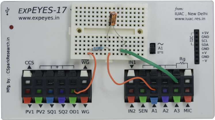
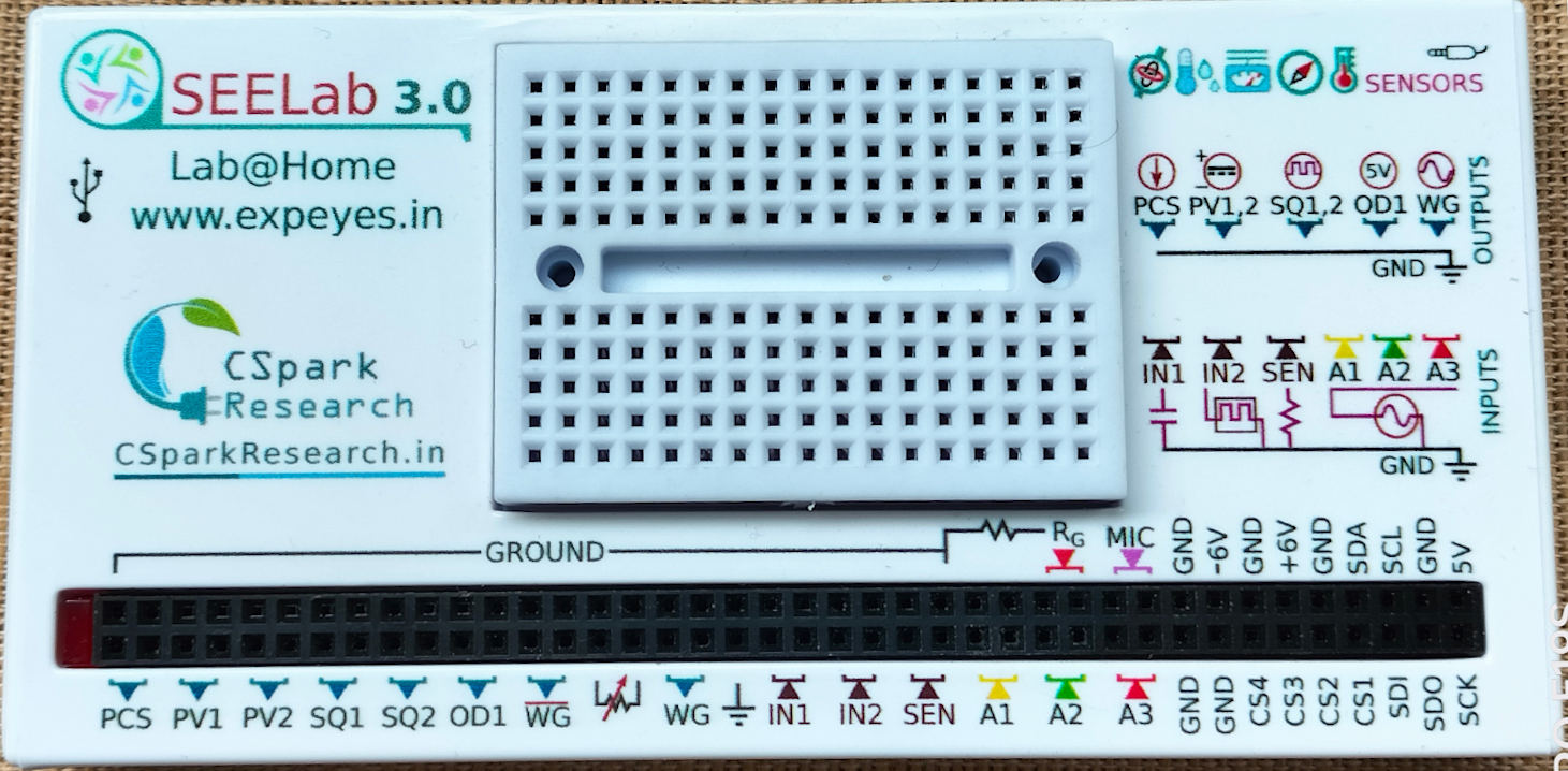
Before proceeding with the experiments, we need to understand the function of various Input/Output terminals of ExpEYES (or SEELab 3). The top panel may be of different types as listed below.
In all the cases the Labels will remain the same (except for some minor upgrades like CCS to PCS). The functions of the Terminals are briefly described below. Most of them occupy two sockets, making parallel connections easier.
PCS : Programmable Current Source (upto 1 mA)
PV1 : Programmable Voltage Source (DC supply). Can be set anywhere from -5V to +5V. You may consider it as a DC power supply.
PV2 : Similar to PV1 but -3.3V to +3.3V range.
SQ1 : A 0 to 5V square wave. Frequency up to 5000 Hz. SQ2 is similar but it is not available when WG is active.
OD1 : Digital output that can be set to 0 or 5 volts.
WG : Waveform Generator. Frequency of the sine wave can be set between 5 Hz and 5000 Hz. The amplitude can be set to 3V, 1V or 80mV from the software.
WG bar: WG output inverted. On SEELab-3, it’s amplitude can be set anywhere from 0 to full scale by connecting an external resistance.
IN1 : Capacitance meter
IN2 : Frequency counter, accepts pulses having heights between 3 to 5V.
SEN : Measures resistance values between 100 ohms to 100 kOhms. Mainly used with sensors like photo-transistors.
A1 and A2 : These are osciloscope inputs but also functions as voltmeters. The input range is -16V to +16V. Maximum sampling rate in 1MHz.
A3 : Similar to A1 and A3 but maximum range is -3.3V to +3.3V only. The input to this can be amplified by connecting an external gain resistor.
MIC : A condenser microphone can be connected between MIC and ground to digitize sound.
Dual DC Supply : A +6V and -6V outputs are provided for performing experiments using op-Amps. The current capability is around 10mA only.
I2C Interface: External I2C sensors can be connected to the pins 5V,GND,SCL and SDA. The software can identify and use several sensors for measuring distance, pressure, temperature, acceleration etc.
It should be noted that the current capability of PV1, WG etc. are around 10mA only. If you connect low value load resistors, the voltage output may reduce. However overloading of the outputs does not cause any damage to the device.
The easiest way to get started is to imagine ExpEYES as a collection of test and measurement equipment like DC power supply, voltmeter, oscilloscope, function generator etc. Instead of switches and knobs fixed on the equipment, they are controlled by buttons and sliders on a Graphical User Interface.
To explore the GUI, the best place to get started is with the Oscilloscope. The scope interface allows you to become familiar with most of the Input/Output terminals. Selecting the Oscilloscope gives a screen as shown below.
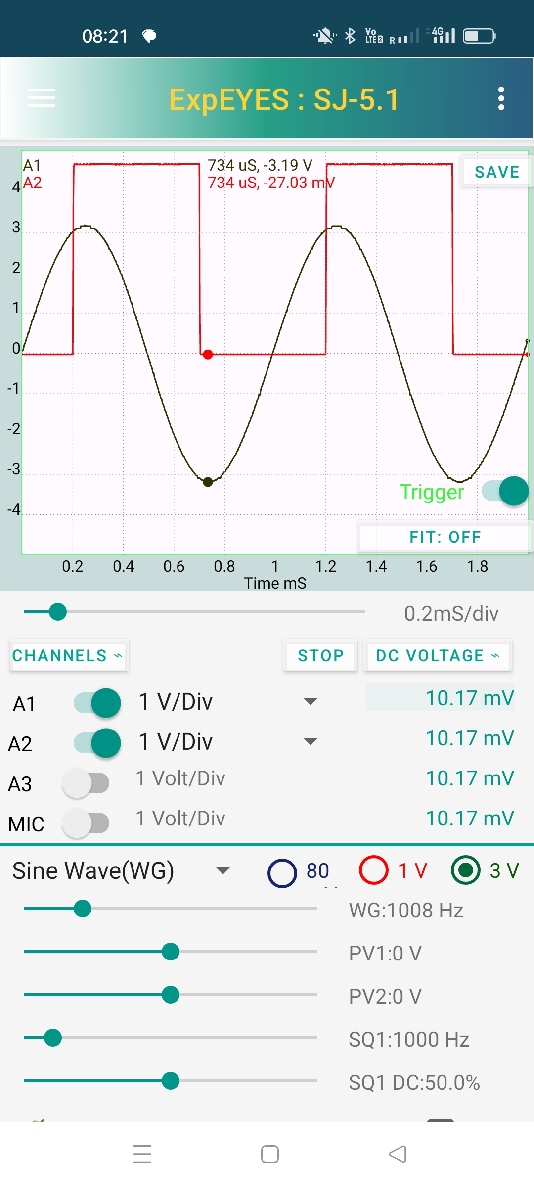
In this case, the input channels A1 and A2 are enabled, using the slide switches. The inputs are set to 1 volt/division, that can be changed for A1 and A2. The time base can be changed using the slider below the graph window.
We have connected WG to A1 and SQ1 to A2, using two external wires. The WG and SQ1 values can be changed using the sliders provided. Tapping on the displayed value pops a text entry window where you can enter a new value.
Moving your finger inside the plot window generates markers on all the traces displaying the time and voltage values.
The traces can be fitted mathematically by selecting the function from a menu. The amplitude, frequency, phase and phase difference values are displayed.
Disable and again enable the trigger to get a popup window where you can set the source and level.
Other Terminals like SEN, IN1, IN2 and OD1 are also accessible from the scope program.
The experiments that can be performed using ExpEYES are organized in to different categories. The section titled ‘School Level’ are open ended explorations to improve the level of understanding about various physical processes. Pressing the Experiments Icon on the main page displays several categories and from that one can select any experiment.
The instructions and connection diagrams are provided with each experiment so that it can be performed without any external documentation. The experiments given in the different sections are briefly described below, mostly providing a protograph of the connections made and a screenshot of the results. Many of them are standard experiments at B.Sc Physics and Electrical/Electronics engineering.
All science experiments involve the measurement/control of physical parameters in a pre-defined sequence. This pre-defined sequence is implemented in software. For example to plot the VI characteristic of a PN junction, the applied voltage is incremented in small steps and the collector voltage and current are measured at each step. Right from the beginning of the PHOENIX project at IUAC during 2005, one of the objectives was to enable the users to design new experiments. To some extent this was done by writing simple program in Python.
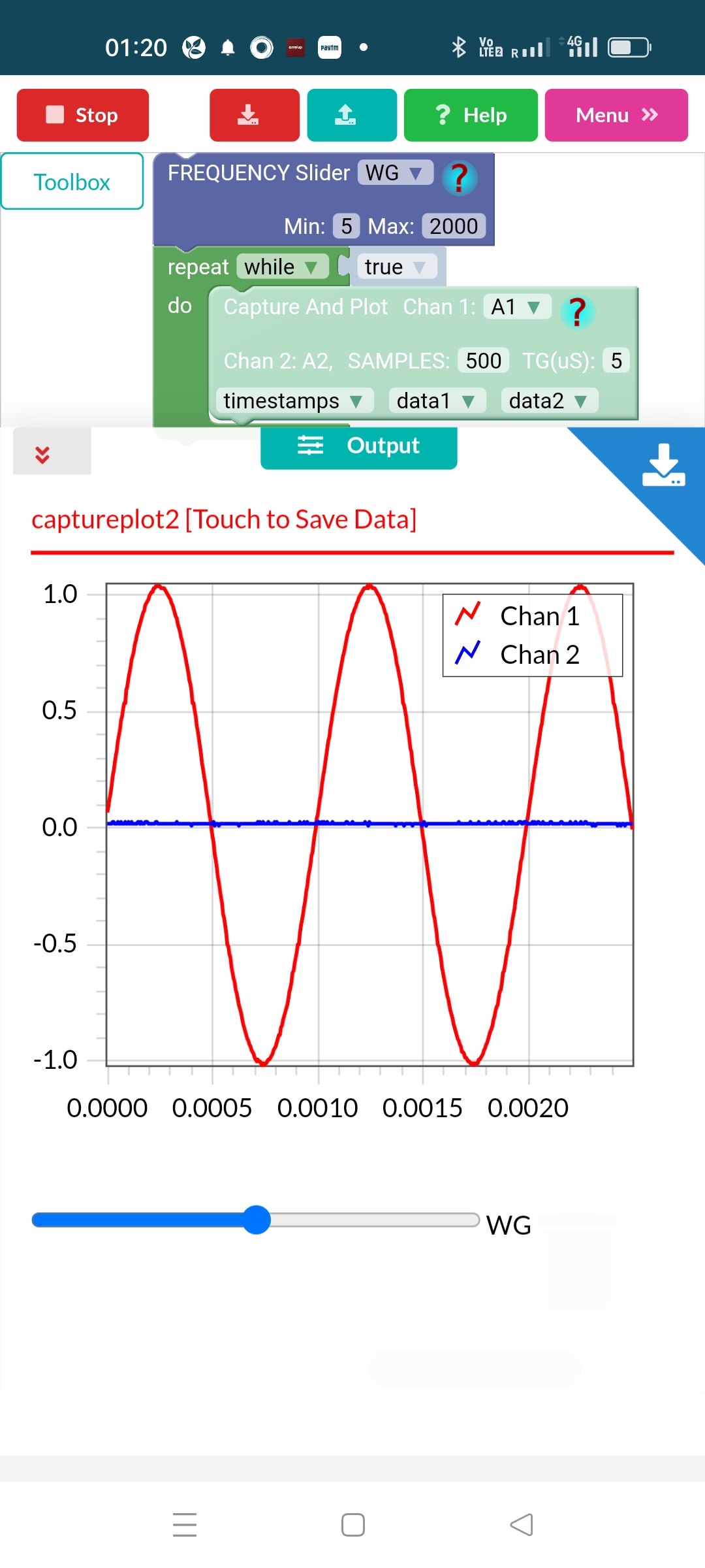
Currently this has been achieved using Visual Programming (MIT Scratch is a popular example). By dragging and dropping functional building blocks one can assemble a program. Here you have blocks for making measurement and control functions on the ExpEYES hardware. The screenshot below shows the program to assemble a two channel scope along with the results.
A Digital Storage Oscilloscope digitizes the input for a given time interval and plot a graph of these voltages against time. This process is repeated in a loop. The ‘Capture2 and Plot’ block implements it. The number of points to be digitized and the time interval between two digitizations can be specified. Another block provides a slider to control the frequency of the waveform generator.
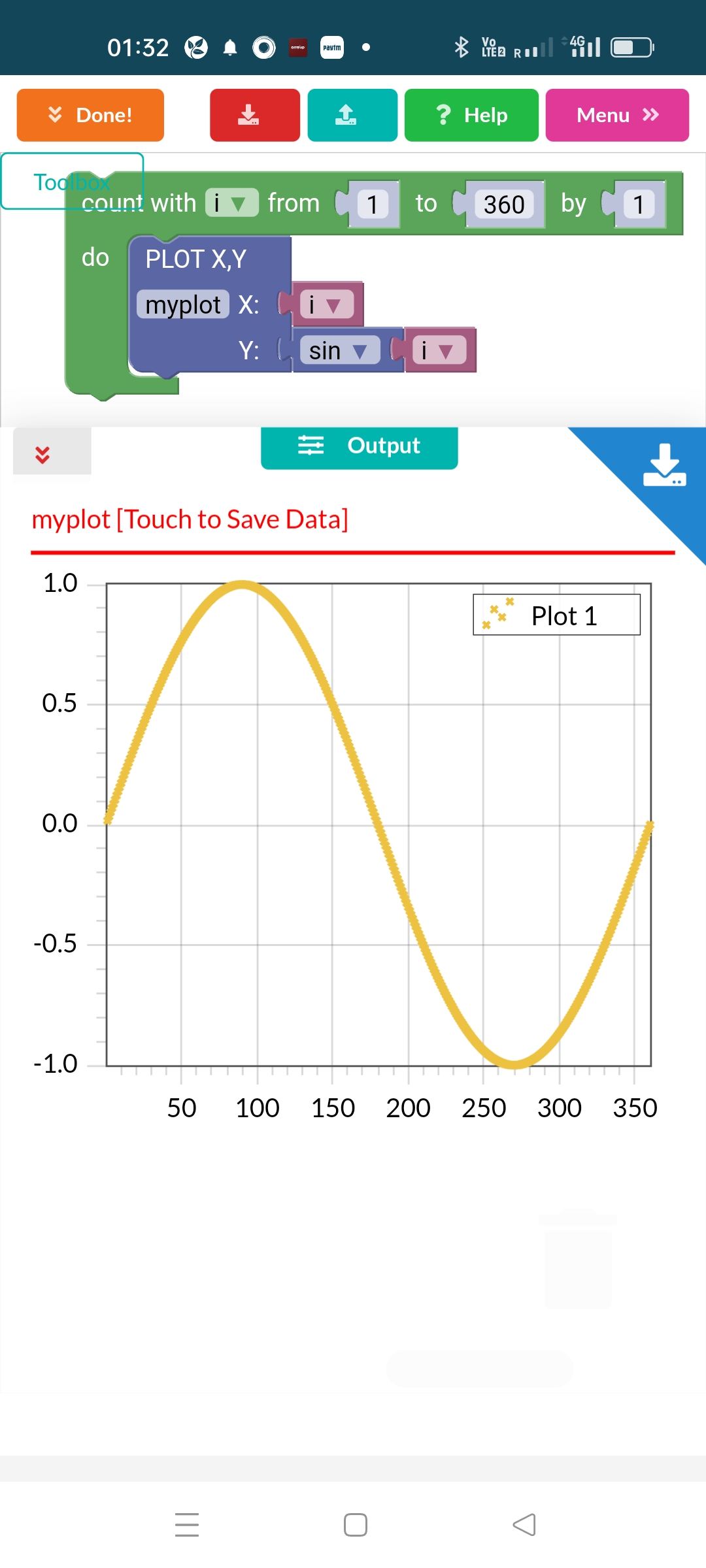
The Visual Programming feature can be used for learning programming skills without the ExpEYES hardware also. The screenshot below shows a sinewave plotted using Visual code.
a short video on using the SEELab App