Resources
Books
Videos
Ajith
The objective is to study the behavior of a RC series circuit under an applied sinusoidal voltage. The resulting voltage amplitudes across the elements and their phase relationships are measured. The connections are shown in the screenshot below.
We have chosen a 1uF capacitor and 1000 Ohm resistor. The applied frequency is chosen as 150 Hz, to start with, because at this value the voltages are almost equally divided and easy to visualize from the graph.
Touching WG pops up a Slider to change the frequency, and Gauge to show it. Tapping on the gauge pops a text entry window where value of the frequency may be typed. In some cases, the value set will be slightly different from what is entered, this is an internal limitation of the waveform generator.
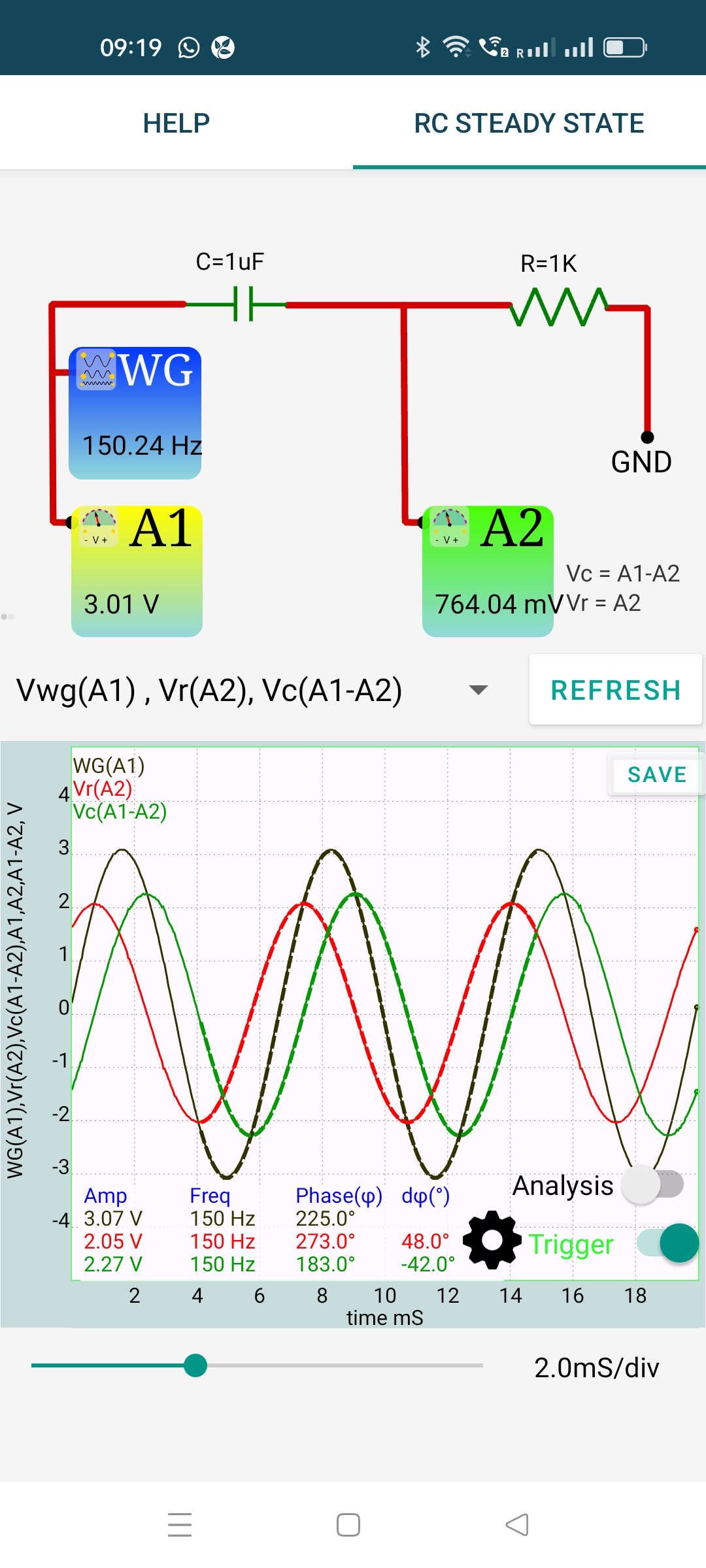
An AC voltage is applied to the RC circuit.The phase of current is same as the voltage across the resistor. The output shows:
It can be seen that the voltage across the capacitor lags behind the current by $ \frac{\pi}{2} $. The phase difference between the applied voltage and current is given by $ \phi=tan{^1}(\frac{Z_C}{R}) $, where $ {Z_C} $ is $ \frac{1}{2\pi f} $. The phase difference is also displayed.
The measured values of the applied voltage, voltage across the capacitor and the voltage across the resistor are also shown. Vector addition should be used to get the total voltage from the voltages across R and C.